


Many decorative accent lights, LED under-cabinet strips, and small desk lamps rely on standard 5-volt USB connections for power. While these low-voltage fixtures are convenient to set up in personal workspaces, their factory switches often create unexpected operational challenges. When paired with automated outlets or wall timers, an internal switch may prevent the fixture from turning back on once electrical current resumes. Learning how to bypass usb light on off switch mechanisms allows users to integrate their favorite low-voltage lights into automated schedules without frustrating manual interventions.
Whether you are modifying clip-on and portable lighting fixtures for a workspace or simply repairing a broken switch housing, understanding direct-current circuit fundamentals is essential. Standard USB cords house dedicated conductors for positive voltage and electrical ground, meaning any bypass requires identifying the correct wire before modifying the cable. With basic wiring techniques and careful insulation, you can bypass an inconvenient switch or swap in an inline solution tailored to your daily setup. Doing so keeps your lighting fully responsive to external power switches and smart control systems.


How to Safely Bypass or Modify a USB Light Switch
Bypassing a USB light switch involves either bridging the internal contacts on an electronic circuit board or splicing the 5-volt power conductors around an inline housing so electricity flows continuously to the light source. The exact modification depends on whether the light uses a physical mechanical rocker, an electronic soft-touch button, or an integrated dimming controller. Mechanical switches can be bypassed by joining the interrupted power line directly, while momentary electronic switches require jumping the internal switching transistor or replacing the cord assembly entirely. Understanding these electrical differences ensures your lighting operates reliably without risking damage to the USB power supply.
Identifying the Switch Type in Your USB Light Assembly
Before attempting any modification, determining the physical and electrical design of the inline switch is critical. Mechanical switches feature a physical rocker or toggle lever that physically makes or breaks contact between copper terminals. When toggled into the on position, the switch maintains a continuous physical bridge that remains closed even when the power supply is unplugged. Because these switches operate purely through mechanical contact, they are the simplest type to modify or leave permanently engaged.
Electronic switches present a different operational structure because they rely on active semiconductor components to control current flow. These switches usually feature a soft push button, a silicone membrane, or a capacitive touch surface rather than a latching mechanical lever. Inside the plastic enclosure, a miniature printed circuit board uses a microcontroller or latching logic chip to detect button presses. Every time electrical current is completely removed, the internal logic resets to an unpowered state that defaults to off.
Multi-function inline controllers introduce another layer of complexity by combining power toggling with brightness or color adjustments. These controllers frequently feature three or four buttons arranged in a compact plastic pod along the cable. They use pulse-width modulation to dim the connected light-emitting diodes or cycle between warm and cool color temperatures. If you bypass such a controller completely, the connected light will typically operate only at its default full brightness and base color spectrum.
Why Smart Plugs Fail with Momentary Electronic Switches
The primary reason homeowners seek to bypass USB switches is incompatibility with upstream home automation hardware. Many people plug low-voltage desk lamps or under-cabinet accent lights into smart wall plugs or smart power strips. When the smart plug turns on at a scheduled time, line voltage energizes the USB power adapter and sends 5 volts down the cord. However, if the lamp contains an electronic momentary switch, the light remains dark until someone physically depresses the button.
This frustration occurs because electronic momentary switches use volatile circuit designs that do not retain their operational state across power interruptions. Unlike a mechanical toggle that remains physically clamped closed, the digital latching transistor requires an active power supply to hold its gate open. Once the smart plug cuts power to save energy, the gate voltage drops to zero instantly. When power returns, the system reboot cycle places the device into standby mode rather than turning on the illumination array.
Resolving this issue is essential for anyone pairing low-voltage fixtures with an automated plug-in light timer or a scheduled wall outlet. For automated scheduling to succeed, the connected fixture must possess an always-on physical state. Bypassing the momentary circuit forces the light diodes to draw power the exact millisecond current reaches the USB plug. This modification allows your smart home ecosystem to handle scheduling, scenes, and remote toggling without manual intervention.
Non-Destructive Solutions Using Switched Extension Cables
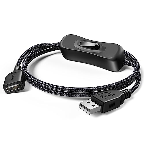
Cutting into existing cords is not always necessary if you prefer to preserve the original condition of your lighting fixture. Several specialized USB extension accessories allow you to introduce mechanical control or permanent pass-through power without altering the lamp itself. By inserting an external switched cable between the power adapter and the light, you can leave the lamp’s existing physical switch set to on. The upstream accessory then takes over daily control duties cleanly.
Products like the ELECTOP 2 Pack Male to Female USB Cable and the BENACES 2 Pack USB Power Switch Cable incorporate dedicated inline rocker switches directly on extension lines. Because these switches use true mechanical contacts, they remain in the closed position indefinitely once toggled on. If you pair one of these cables with a fixture that has a mechanical switch, you can leave both switches closed to guarantee instant power-up via a smart wall plug. Similarly, the ANDTOBO USB Switch Extension Cable provides an inline toggle switch while supporting standard power delivery over its 3.3-foot length.
Another non-destructive route involves adding a wireless radio-frequency controller module between the power block and the fixture. Devices such as the DC 5V USB on Off Wireless Remote Control Switch or the Faizpors 5V 9v12v USB Wireless Remote Control ON Off Switch act as external power relays. These modules plug directly into standard USB ports and allow you to toggle power using a wireless handheld remote. While this approach does not alter an internal momentary switch, it provides remote control convenience for lamps featuring mechanical switches located in hard-to-reach places.
Tools and Safety Preparation for 5V Low-Voltage Circuits
Working on 5-volt direct-current wiring is significantly safer than handling 120-volt alternating-current household circuits, but basic electrical discipline remains essential. Before beginning any modification, completely disconnect the USB cable from the wall charger, computer port, or portable battery pack. Never cut into or solder any cable while it is connected to a live energy source. Working on a disconnected cord eliminates the risk of short circuits that could destroy the power supply or damage connected components.
Gathering the appropriate tools ensures clean splices and reliable insulation throughout the modification process. You will need a pair of precision wire strippers capable of handling fine gauge conductors between 22 AWG and 28 AWG. Small flush cutters, needle-nose pliers, a digital multimeter, and a soldering iron with fine-tip solder are also helpful. For insulation and mechanical protection, procure dual-wall adhesive heat-shrink tubing and high-quality electrical tape.
A digital multimeter is especially valuable for confirming wire continuity and verifying circuit polarity before joining lines. Even though standard USB pinouts follow established color conventions, low-cost decorative lighting cords do not always adhere strictly to standard guidelines. Using the continuity or resistance setting on your multimeter lets you trace the path of each conductor from the USB plug to the switch terminals. Verifying these connections beforehand prevents accidental short circuits between positive voltage and ground.
Step-by-Step Procedure to Hardwire a Mechanical Inline Switch
Bypassing a purely mechanical rocker switch is a straightforward task that eliminates the physical break in the positive power conductor. Begin by inspecting the plastic switch housing along the cable to determine how it is assembled. Most mechanical inline housings consist of two snap-fit halves secured by plastic clips or small Phillips screws. Carefully insert a small flat-head screwdriver along the seam to pry the housing open and expose the internal wiring.
Once inside, observe how the internal conductors are routed through the terminal posts. In a typical single-pole mechanical switch, the negative ground wire passes directly through the housing without interruption. Only the positive power conductor, which is usually red, is severed and soldered to the two brass switch terminals. Confirm that the uninterrupted conductor remains intact and undamaged before proceeding with the positive wire bypass.
To bypass the switch mechanism, use flush cutters to snip the two ends of the positive conductor as close to the switch terminals as possible. Strip approximately one-quarter inch of insulation from both exposed wire ends using precision wire strippers. If you plan to solder the connection, slide a piece of narrow heat-shrink tubing over one of the wire leads before joining them. Twist the bare copper strands tightly together to create a solid mechanical bond.
Heat the twisted joint with your soldering iron and apply electrical solder until the molten metal flows thoroughly through the copper strands. Allow the solder joint to cool completely before sliding the heat-shrink tubing over the exposed connection. Shrink the tubing using a heat gun or the warm shaft of your soldering iron to create an insulated seal. Finally, wrap the spliced section in protective outer tubing or reassemble the original housing around the bypass to provide physical strain relief.
Bypassing Electronic Push Buttons and Touch Switch PCBs
Modifying an electronic momentary switch or touch-sensitive module requires a slightly different approach due to the presence of active circuit components. Open the inline controller housing carefully using a pry tool, taking care not to tear the delicate circuit traces inside. Inside, you will find a small printed circuit board populated with surface-mount resistors, capacitors, and an integrated switching transistor. This transistor acts as an electronic gate that interrupts the flow of direct current.
To permanently bypass the switching logic, you must identify the switching transistor that gates power to the light-emitting diodes. In most 5-volt direct-current circuits, this component is a small three-pin surface-mount MOSFET located near the output lead. The three pins correspond to the gate, source, and drain terminals of the semiconductor. By bridging the source and drain terminals with a tiny drop of solder, you create a permanent electrical path that allows current to flow continuously regardless of the controller logic.
If circuit board soldering appears too delicate, a simpler alternative is to remove the entire electronic switch module from the cable completely. Cut the USB cable roughly one inch on either side of the plastic switch enclosure using sharp flush cutters. Strip back the outer jacket on both cut cable ends to reveal the insulated conductors inside. Splicing the matching positive and negative conductors directly together eliminates the entire problematic circuit board from the electrical loop.
When splicing across the cut section, pay close attention to wire coloration and function. Join the positive power lead from the male USB plug to the positive lead entering the light fixture, and repeat the process for the ground conductors. If the cable includes white and green data wires, trim them flush and leave them unconnected, as standard lighting fixtures do not require data communication. Seal each individual wire splice with heat-shrink tubing before applying an overall sleeve to secure the entire joint.
Replacing Problematic Controllers with Dedicated Inline Hardware
Completely bypassing a switch causes the connected light to run continuously at full output, which is not always desirable for ambient or workspace lighting. If your fixture originally included dimming or brightness settings that you wish to retain, replacing the faulty module with an analog controller is an effective compromise. Analog controllers use mechanical potentiometers that hold their position even when upstream power is shut off. This design ensures that your preferred brightness level returns immediately when a smart plug energizes the cord.
Hardware options like the Maxmoral LED Strip Light Dimmer Switch 5V DC USB feature a rotary dial that mechanically adjusts power output without resetting. Similarly, the Myuiao 2Pcs White DC5V USB LED Dimmer Extension provides inline dimming control designed specifically for low-voltage LED lamps. Because these devices rely on physical rotary potentiometers or persistent memory circuits, they do not default to an unpowered state after a power outage. Inserting one into your cable line maintains dimming flexibility while restoring compatibility with automated timers.
For applications requiring specialized connectivity, devices like the USB Power Switch with Data & Charging Support or multi-pack inline cords like the ThtRht 4 Pack USB Extension Cable with Switch offer practical alternatives. These ready-made cables feature robust physical toggle rockers integrated into molded cord jackets. Replacing an unreliable electronic switch with a dedicated pre-assembled cable reduces modification time while delivering durable mechanical reliability. You can splice the female end directly onto your lamp leads or use standard male-to-female connectors to avoid soldering altogether.
Managing Voltage Drop, Current Limits, and Thermal Safety
Modifying low-voltage wiring requires careful attention to electrical load ratings and wire gauge specifications to prevent overheating. Most standard USB 2.0 cables utilize slender 28 AWG or 24 AWG conductors designed to carry modest currents between 0.5 and 2 amperes. If your modified lighting array draws near the upper limit of your power adapter, undersized conductors can introduce noticeable resistance. High resistance causes voltage drop along the cable, which dims the light output and generates unwanted heat within the wire jacket.
Poorly executed wire splices represent another common source of localized electrical resistance and potential failure. Loose mechanical twists or cold solder joints restrict the flow of direct current, creating a focal point where thermal energy accumulates during extended operation. To avoid heat buildup, always ensure solder joints are fully wetted and structurally sound before insulating them. Utilizing adhesive-lined heat-shrink tubing further reinforces the splice against oxidation, moisture ingress, and mechanical vibration over time.
Always verify that your USB wall adapter provides adequate current capacity for the connected lighting fixture. A standard 5-volt adapter rated for only 1 ampere may become hot or trigger internal thermal shutoffs if connected to a large LED strip that demands 2 amperes or more. Check the input specifications printed on your fixture and match them to an adapter with equal or slightly higher amperage ratings. Maintaining appropriate power margins ensures that your bypassed lighting setup runs cool and dependable for daily use.
Testing, Verification, and Post-Modification Care
Once all wire modifications and insulation steps are complete, perform a thorough bench test before placing the light into everyday service. Plug the modified USB cable into a standalone power bank or an inexpensive USB wall charger rather than directly into an expensive computer port. If an accidental short circuit exists, a standalone adapter will trip its internal overcurrent protection safely without harming costly electronic hardware. Verify that the light illuminates immediately upon connection without flickering or dimming.
Allow the light fixture to run continuously for thirty minutes while monitoring the temperature of the spliced wire section. The insulated joint should remain cool to the touch and match the ambient temperature of the surrounding cord. If you notice any warming, disconnect power immediately and inspect the splice for high resistance, damaged strands, or improper solder bonding. Addressing electrical irregularities promptly ensures the long-term safety and reliability of your modified lighting fixture.
Successfully bypassing an inconvenient USB switch transforms a frustrating manual light into a fully integrated smart lighting component. By selecting the appropriate method, whether jumping a switch terminal, splicing conductors, or adding an inline mechanical cable, you establish reliable always-on functionality. Keep all connections properly insulated and avoid pulling or straining the modified joint during routine cleaning or repositioning. With thoughtful assembly, your customized low-voltage lighting will deliver steady illumination whenever your automated home controls call for it.




Write Your Review
No reviews yet. Be the first to share your experience!