


Flickering room fixtures, unresponsive wall controls, and sudden circuit dropouts often leave homeowners wondering whether a light fixture or its controlling switch has failed. Diagnosing an electrical issue starts with isolating the control mechanism before replacing expensive drivers or fixtures. Knowing %how to check a switch with a multi meter% provides immediate clarity on whether mechanical contacts inside the toggle or rocker have worn out. A simple continuity or resistance measurement reveals whether electrical current can complete its path when toggled.
Testing wall controls safely requires basic electrical precautions, proper meter dial settings, and an understanding of single-pole versus multi-location circuits. While routine care outlined in our LED lighting maintenance guide helps preserve fixture components, internal switch contacts inevitably experience physical wear and arc degradation over time. Using a digital multimeter allows you to diagnose standard toggles, decorative rockers, and specialized controls without guessing. With the circuit fully powered down, a quick verification takes only minutes and prevents unnecessary hardware replacements.


Step-by-Step Guide to Testing Switches With a Multimeter
Testing an electrical switch with a digital multimeter requires measuring continuity or resistance across its terminal screws while the power is completely disconnected. A functioning single-pole switch will show continuous electrical flow (near zero ohms or an audible beep) when toggled to the ON position, and complete electrical isolation (infinite resistance, often displayed as O.L) when toggled to the OFF position. Any measurement that shows high resistance when closed or partial continuity when open indicates internal contact failure or carbon buildup. This quick bench test removes guesswork when troubleshooting faulty lighting circuits before you begin replacing costly fixture hardware.
Understanding How Multimeters Measure Switch Integrity
Mechanical light switches operate by physically bridging two or more conductive metal contacts inside an insulated plastic housing. When you flip the toggle, a spring-loaded arm snaps against the stationary contact to close the circuit and allow alternating current to reach the light fixture. Over years of operation, electrical arcing slowly pits these contact surfaces, leaving non-conductive carbon deposits that eventually disrupt power delivery. A multimeter evaluates this internal junction by sending a tiny direct current from its internal battery across the switch terminals.
Because the test meter supplies its own low-voltage signal, testing must always occur on an isolated, unpowered switch. Measuring resistance in ohms lets you see exactly how cleanly those metal contacts mate when the actuator moves. A reading of less than one ohm signifies a healthy path with minimal electrical friction, whereas fluctuations above five ohms suggest internal degradation. Understanding this basic mechanical relationship helps you distinguish between external wiring faults and physical switch failure.
Electrical Safety and Power Disconnection Protocol
Safety remains the primary concern whenever you work around residential or commercial electrical systems. Before touching any terminal screws or removing switch plates, you must de-energize the controlling branch circuit at your main breaker panel. Flipping the wall toggle to the off position is never sufficient because live line voltage remains present at the incoming terminal. After switching off the breaker, lock the panel door or place a warning tag over the switch to prevent accidental re-energization while you work.
Always verify that voltage is completely absent before unscrewing the switch from its electrical box. A non-contact voltage tester provides a reliable first check when held against the terminal screws and insulated wire jackets. Once the faceplate is off, touch the multimeter test leads set to AC voltage between each terminal screw and the grounded metal box or bare ground wire. A zero-volt reading confirms that the circuit is dead and that it is safe to loosen the terminal screws and remove the switch for bench testing.
Dial Settings: Choosing Continuity or Resistance Modes
Most digital multimeters, including compact models like the Marhynchus digital multimeter with auto-switching, provide both continuity and resistance modes. The continuity mode features a small sound wave or diode symbol on the selection dial. When continuity mode is active, the meter sounds a continuous tone whenever the test leads touch a low-resistance path under thirty to fifty ohms. This audible feedback allows you to test switches rapidly without constantly looking back at the meter display screen.
The standard resistance setting, indicated by the capital Greek omega symbol, provides a precise numerical value rather than just a tone. If your meter lacks an audible continuity function, set the rotary dial to the lowest resistance range, typically two hundred ohms. An open circuit will display “1”, “O.L” (open loop), or a flashing indicator depending on your specific meter model. When the switch contacts close cleanly, the display numbers drop rapidly down toward zero, confirming a solid connection.
Step-by-Step Testing for Single-Pole Light Switches
Single-pole switches are the most common wall controls in residential homes, featuring two brass terminal screws and one green grounding screw. To begin testing, place the switch on a non-conductive wooden or plastic work surface. Connect one multimeter probe to the first brass terminal screw using an alligator clip or firm manual pressure. Attach the second probe to the remaining brass terminal screw, ensuring that your fingers do not touch the metal probe tips directly during the measurement.
Move the switch toggle to the OFF position and observe the digital display. In the OFF position, the meter should register an open loop with no sound, proving that the internal contacts have successfully separated. Next, flip the toggle to the ON position while maintaining steady probe contact with both brass screws. The meter should instantly emit a steady tone or display a resistance value near zero point zero to zero point four ohms, verifying proper continuity.
Gently wiggle the toggle lever back and forth while it remains in the ON position. A good switch maintains steady continuity and consistent resistance despite slight manual vibration on the toggle. If the meter reading spikes, flickers, or loses continuity during light movement, the internal contact spring has weakened. In that situation, replacing the switch is necessary because loose contacts generate heat and cause fixture flickering when paired with affordable indoor fixtures across living spaces.
Diagnosing Three-Way and Four-Way Lighting Switches
Multi-location lighting circuits use three-way and four-way switches to control lights from two or more wall locations. A three-way switch features three active screw terminals: one dark common screw and two lighter-colored traveler screws. Identifying the common terminal is crucial because it serves as the electrical bridge directing power between the two travelers. Before testing, inspect the switch body stamping to confirm which screw is marked as the common point.
Attach one meter probe firmly to the dark common screw terminal. Place the second probe against traveler screw A, then flip the toggle up and down to check for alternating continuity. You should find solid continuity in one position and an open loop in the opposite position. Then, move that second probe to traveler screw B and repeat the toggle sequence. The switch should now show continuity in the opposite toggle position, proving that the internal diverter cleanly switches paths between travelers.
Four-way switches are slightly more complex because they contain four traveler terminals arranged in paired sets. To test a four-way switch, test continuity between input terminal one and output terminals A and B across both toggle positions. In one position, terminal one connects to output A, while in the reverse position, it crosses over to output B. If any terminal combination fails to switch or shows erratic high resistance, replace the unit to restore smooth multi-switch lighting control.
Testing Specialized Dimmer Switches and Electronic Controls
Standard continuity tests work exceptionally well on mechanical switches, but electronic dimmers require a modified diagnostic approach. Traditional phase-cut dimmers and modern smart switches contain solid-state semiconductors, microprocessors, and internal capacitors rather than simple mechanical contacts. Because these internal electronic components require a threshold voltage to conduct, a basic multimeter battery cannot close the semiconductor gate. Consequently, an unpowered smart switch will almost always display an open loop on a resistance meter.
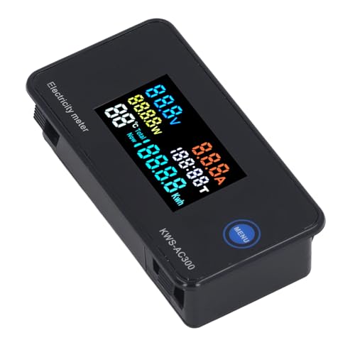
For electronic dimmers that feature a physical mechanical air-gap switch, you can test that specific isolation switch using standard continuity mode. Pulling the air-gap lever outward must break continuity completely, offering absolute safety during bulb replacements. If you are diagnosing a smart switch like a WiFi-enabled smart power meter switch, voltage-drop testing on an active, carefully supervised circuit is generally required. Always consult the manufacturer wiring diagrams for electronic switches to avoid misinterpreting semiconductor behavior as hardware failure.
Interpreting Multimeter Readings and Common Failure Symptoms
Interpreting digital multimeter readings requires understanding the difference between zero resistance, fractional resistance, and an open circuit. A reading of zero point zero ohms indicates zero electrical resistance, representing a perfect closed circuit path. An open loop reading, frequently abbreviated as O.L or indicated by a lone digit “1” on manual meters, indicates infinite resistance. When a switch toggle is ON, any reading that stays at open loop confirms that the internal contact arm has snapped or burned out completely.
Intermediate resistance readings between two ohms and several thousand ohms represent a common yet deceptive failure mode. Contamination, pitted copper contacts, or dried internal lubricants create partial electrical conductivity that chokes current flow. When high resistance exists across a closed switch, voltage drops across the switch instead of reaching your lighting load. This condition leads to buzzing wall boxes, dim LED illumination, and excess heat generation that can pose a fire hazard if left unaddressed.
Tool Selection: Multimeters, Network Testers, and Specialized Instruments
Selecting the right diagnostic meter makes electrical troubleshooting much faster and more accurate for property owners. Basic digital multimeters with autoranging capabilities automatically select the correct resistance scale, reducing operator error during testing. Advanced multi-testers, such as the Fabater network cable tester multimeter or combination electrician diagnostic tools, bundle continuity functions with cable tracing and non-contact voltage detection. These multi-use tools prove useful when tracing unlabeled switch legs through finished walls or attics.
Specialized industrial installations or heavy motor control circuits may also encounter power rectifying devices alongside mechanical controls. Devices like industrial brake rectifiers convert alternating line voltage into direct current for mechanical holding brakes. While testing a brake rectifier requires checking built-in internal diodes rather than a simple mechanical contact, the same digital multimeter handles both tasks easily. Having a reliable meter equipped with sturdy test leads ensures you can diagnose standard wall switches as well as heavy-duty lighting equipment and shop gear.
Avoiding Testing Errors and Contact Oxidation Traps
Even experienced DIY homeowners occasionally encounter misleading multimeter readings due to common procedural mistakes. The most frequent error involves leaving test wires connected to the switch while trying to measure continuity. If the switch remains connected to circuit conductors, the multimeter may read back-feed loops through connected light fixtures or parallel loads. To ensure accurate results, always remove at least one conductor from the switch terminal before taking any resistance measurement.
Another common issue stems from oxidized probe tips or dirty terminal screws that artificially introduce high resistance. Copper and brass screw heads develop an invisible layer of tarnish when exposed to ambient moisture over several years. If your initial reading shows fluctuating numbers, press the sharp tip of your probe firmly into the screw metal or scratch the surface lightly to establish clean contact. Cleaning the probe tips periodically with a dry cloth ensures your meter detects genuine internal switch resistance rather than surface oxidation.
Reinstallation, Grounding, and Circuit Verification
Once testing confirms that your switch operates properly, you can safely reinstall the component back into the electrical junction box. Inspect the conductor ends and strip back any damaged or nicked copper wire to ensure a clean mechanical connection. Loop the solid copper wire clockwise around each brass terminal screw before tightening down the terminal with a hand screwdriver. Connecting wires in a clockwise direction ensures that tightening the screw draws the wire loop tighter rather than pushing it outward.
Always reconnect the bare or green equipment grounding conductor firmly to the green ground screw on the switch frame. Proper grounding ensures that any stray fault current trips the circuit breaker instantly rather than energizing the switch plate screws. Carefully fold the insulated conductors back into the electrical wall box in an accordion fashion to avoid pinching wires against the box edges. Fasten the switch mounting yoke flush with the drywall, install your decorative wall plate, and restore power at the main electrical panel.
Knowing how to evaluate an electrical switch with a digital multimeter turns an intimidating lighting failure into a predictable diagnostic process. By isolating the switch from power, selecting the continuity or resistance scale, and checking each toggle position, you pinpoint the exact source of trouble within minutes. This straightforward verification confirms whether a replacement switch is truly necessary or if the fault lies elsewhere in your fixtures, drivers, or branch wiring. Taking the time to test components systematically preserves your lighting hardware and keeps your home electrical system operating safely.





Write Your Review
No reviews yet. Be the first to share your experience!