


A sudden alert on your dashboard or a quick exterior walkaround can reveal a dark tail lamp housing that puts road safety at risk. Maintaining dependable rear signaling ensures following motorists notice your vehicle decelerating long before an unexpected collision occurs. Learning how to replace a brake light is one of the most accessible maintenance procedures you can tackle in your driveway or garage. Using reliable lighting, like hands-free headlamps for maintenance tasks, makes navigating cramped trunk spaces and rear quarter panels straightforward. A systematic approach helps protect delicate plastic trim clips and keeps your electrical connections pristine throughout the swap.
Modern vehicles rely on specific bulb styles, ranging from classic dual-filament incandescent bulbs to modern multi-diode replacements such as the AUXITO Upgraded 7440 7443 LED Bulb Red for Tail. Upgrading or swapping an unlit diode restores essential luminosity and preserves proper signaling across adverse weather conditions. Understanding how to pull the housing, separate the wiring harness, and verify socket polarization prevents unnecessary electrical headaches down the road. Taking the time to inspect your bulb socket and gaskets guarantees that moisture never compromises your fresh lighting installation.

Comprehensive Guide to Brake Light Replacement and Bulb Setup
Replacing an unlit rear illumination source restores critical vehicle signaling and keeps your driving record free of equipment citations. The entire physical process typically requires fifteen to thirty minutes when using standard hand tools and following proper safety steps. While modern vehicle designs vary between interior trunk access panels and exterior lens assemblies, the fundamental procedure centers on releasing the socket and seating a fresh bulb. Taking time to inspect the wiring harness and weather seals ensures your new components deliver reliable performance across changing seasons.
Understanding Brake Light Assemblies and Socket Mechanics
Rear lighting modules differ significantly across vehicle manufacturers, but most passenger cars and light trucks employ one of two mounting designs. Some vehicles permit direct access to the bulb sockets through removable service doors or pull-away trunk carpeting located directly behind the taillight bucket. Other vehicle architectures require you to unbolt the exterior taillight housing completely from the rear quarter panel to access the bulb carriers. Recognizing which physical layout your vehicle utilizes prevents unnecessary fastener removal and protects internal sheet metal clips from breakage.
The socket itself serves as both the electrical contact point and the primary moisture seal for the interior reflector cavity. Most automotive taillights utilize a quarter-turn bayonet socket equipped with a pliable silicone or rubber O-ring. Rotating the plastic socket collar approximately forty-five to ninety degrees counterclockwise disengages the locking tabs and allows the assembly to slide free. Examining the socket shell for heat discoloration, melted plastic, or corrosion helps you identify potential underlying circuit resistance before installing a replacement.
Identifying Bulb Formats and Cross-Reference Standards
Automotive brake light fixtures utilize standardized socket numbering systems to ensure electrical and mechanical compatibility across brands. Popular wedge-base designations include the 7440 and 7443 footprints, which share mechanical dimensions with T20, W21W, 7441, 7444, and 7443LL variants. The primary functional distinction lies in whether the circuit operates as a single-intensity or dual-intensity lighting channel. Single-function bulbs illuminate only during active braking, whereas dual-filament or dual-circuit units provide low-intensity running light output alongside high-intensity stop signaling.
Socket wiring schemes introduce another vital distinction between standard North American wiring and CK ground configurations. In a standard wedge socket, the ground and positive terminals sit on opposing sides of the plastic base, while CK sockets group common contacts differently. Modern multi-fit components such as the AUXITO Upgraded 7440 7443 LED Bulb Red for Tail incorporate non-polarity internal circuitry designed to operate across standard and CK wiring formats. This universal terminal design eliminates electrical shorts and ensures consistent current delivery regardless of socket pin layout.
Consulting your owner manual remains a prudent preparatory step because online parts finders occasionally list conflicting trim-level information. Pulling the unlit bulb and reading the stamped industry number along the plastic or glass collar provides definitive verification. If the stamped numbers are obscured by road grime or thermal wear, comparing the pin arrangement against standard socket diagrams resolves any lingering doubt. Verifying these dimensional and electrical details prior to installation prevents frustrating returns and delays.
Workspace Safety and Tool Preparation
Working around automotive electrical systems demands basic safety precautions to safeguard both yourself and the vehicle electronics. Park the automobile on a level concrete surface, engage the emergency brake firmly, and switch off the ignition completely. Removing the key fob or disconnecting the negative battery terminal eliminates the risk of an accidental short circuit while handling bare wiring terminals. Allowing the rear lighting assembly to cool for several minutes prevents painful fingertip burns caused by hot incandescent glass capsules.
Gathering the proper hand tools before opening the vehicle trunk streamlines the entire mechanical operation. Most modern installations require a set of plastic pry bars, a standard ten-millimeter socket with a small ratchet, and clean nitrile gloves. Utilizing non-marring plastic levers protects delicate automotive clearcoat and prevents cracking painted bumper surfaces when dislodging lens assemblies. Clean gloves keep natural skin oils off bulb surfaces, preserving clarity and preventing localized thermal stress on surrounding housings.
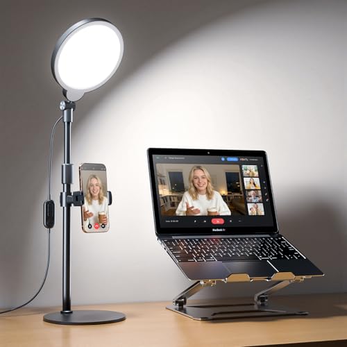
Adequate workspace illumination is critical when peering into dark trunk recesses or evaluating fine socket contacts. If you remove the socket harness to inspect terminal pins on a garage workbench, utilizing focused task lamps for precision inspection provides shadow-free clarity. Clear visibility allows you to spot hairline cracks in plastic retaining tabs, green copper oxidation, and loose spring contacts before snapping components together. Investing five minutes in clean workspace setup prevents dropped screws and missing retaining clips.
Step-by-Step Procedure for Reaching the Lamp Assembly
Accessing the rear light cavity begins by identifying whether your vehicle uses interior liner hatches or external mounting hardware. For vehicles featuring internal access panels, open the trunk or rear liftgate and locate the plastic access doors integrated into the felt side trim. Pry open the plastic door with a flat nylon tool to expose the rear of the taillight housing and wiring bundle. If your vehicle lacks dedicated service doors, gently pry loose three or four plastic retainer pins to peel the trunk carpet inward.
Vehicles requiring complete taillight housing removal typically expose two or three retaining screws once the trunk lid or tailgate is elevated. Use your ratchet or Phillips screwdriver to remove these fasteners, storing them securely in a magnetic parts tray. Once the hardware is free, grip the housing with both hands and pull directly rearward along the vehicle axis. Modern taillights utilize metal ball studs pressed into nylon grommets on the quarter panel, which disengage with moderate, steady outward pressure.
Never pry aggressively between the exterior body sheet metal and the plastic taillight lens with steel tools. Applying uneven leverage against the lens corner can easily fracture acrylic lenses or gouge automotive paint down to bare steel. If the housing feels stubborn, apply gentle rhythmic pressure while pulling straight back until the ball studs slide out of their rubber sockets. Support the freed assembly with one hand so it never hangs suspended by delicate electrical wiring harnesses.
Extracting the Expired Bulb and Installing the Replacement
Once the rear of the lamp assembly is accessible, locate the specific socket corresponding to the brake light chamber. Trace the wiring harness to confirm you are servicing the stop lamp socket rather than the reverse or turn indicator position. Grasp the plastic socket collar firmly and twist it approximately one-quarter turn counterclockwise until the locking detent releases. Pull the socket straight out of the housing bore, taking care not to drag the bulb against the reflective internal chrome chamber.
Removing a standard wedge-base bulb simply requires grasping the glass envelope and pulling straight out of the terminal clip. If you encounter a bayonet-style metal base, push the bulb lightly into the socket while rotating it counterclockwise before withdrawing it. Inspect the metal leaf spring contacts inside the socket bore to ensure they remain springy and free of burnt residue. Lightly applying automotive dielectric grease to the socket contacts helps repel road moisture and prevents future electrical oxidation.
Insert your new bulb firmly into the socket receiver until you feel it click securely into the retention brackets. Modern components like the AUXITO 7443 LED replacement feature non-polarity engineering, allowing you to insert the wedge base in either orientation without reversing circuit flow. The solid electroplated housing and precisely spaced surface-mount diodes slide smoothly into standard reflector openings. Ensure the bulb sits plumb and fully bottomed out within the terminal base so physical vehicle vibration cannot dislodge it.
Pre-Reassembly Testing and CANbus Circuit Management
Testing your new illumination before reinstalling trim pieces or tightening exterior fasteners prevents redundant disassembly. Reconnect the negative vehicle battery terminal if it was disconnected earlier in the procedure, keeping the loose socket visible. Have an assistant depress the brake pedal firmly while you observe the illuminated bulb directly from behind the vehicle. Verify that the unit lights up instantly and exhibits a dramatic brightness contrast between baseline running mode and active braking mode.
Modern vehicles equipped with computerized body control modules monitor circuit resistance continuously to detect burnt filaments. Because high-efficiency LED replacements consume approximately 5.5 watts compared to traditional high-draw halogen bulbs, sensitive vehicle monitoring systems may register a false bulb-out warning. In some computer-controlled platforms, this reduced electrical load can cause hyper-flashing on shared signal circuits or persistent dashboard warning lights. These symptoms do not indicate a defective bulb, but rather reflect an ultra-sensitive diagnostic computer detecting lower current draw.
Resolving computerized resistance warnings requires installing an external load resistor or vehicle-compatible flasher relay into the circuit. Wiring a standard fifty-watt, six-ohm gold-anodized resistor in parallel across the positive and ground leads simulates traditional filament current draw. Always mount external load resistors directly against vehicle chassis sheet metal, as these aluminum components dissipate heat rapidly during sustained braking. Alternatively, contacting the bulb manufacturer often yields plug-and-play wiring decoders that bypass diagnostic error messages without splicing factory harnesses.
Reinstalling Housings and Preserving Weatherproof Seals
Reassembling the vehicle lighting system demands meticulous attention to perimeter gaskets and socket O-rings. Before seating the socket into the reflector opening, wipe the rubber gasket clean of road dust, grit, and loose debris. Align the variable-width locking tabs on the socket collar with the matching cutouts on the taillight housing opening. Push the socket flush against the housing collar and rotate it clockwise until the plastic latch clicks into its mechanical stop.
If you unbolted the entire exterior lens assembly, carefully align the forward guide pins and rear ball studs with their body grommets. Push the housing straight forward with firm, even palm pressure until the alignment pins snap into their factory mounting points. Inspect the perimeter seam between the taillight lens and vehicle sheet metal to ensure consistent body panel gaps. Reinstall the mounting screws or retaining nuts by hand before tightening them evenly with your ratchet to prevent cracking the mounting tabs.
Finish the mechanical installation by reinstalling trunk carpeting and pressing all plastic push pins securely into place. Make certain trunk interior trim does not pinch or chafe against the newly routed wiring harness or external resistor assemblies. Run a gentle stream of water over the rear taillight lens during your next vehicle wash to confirm the perimeter seals prevent internal condensation. A tight, clean installation protects both vehicle electronics and trunk storage areas from moisture accumulation.
Diagnostic Steps for Post-Installation Lighting Irregularities
If your freshly installed brake light fails to illuminate during pedal actuation, begin diagnosis at the socket connection. Remove the bulb and inspect the internal metal leaf contacts to ensure they have not flattened down against the socket floor. Gently lifting the metal contact prongs slightly outward with a small wooden toothpick restores tight physical friction against the bulb pins. Reinsert the bulb firmly and repeat the actuation test to verify solid electrical continuity.
A non-responsive bulb across both driver and passenger sides often points to a blown automotive fuse or a failed brake pedal switch. Locate the vehicle interior or under-hood fuse block and reference the diagram for the stop lamp circuit fuse. Pull the designated fuse with a plastic puller tool to inspect whether the internal metallic bridge has melted or separated. Replacing a blown fuse with an identical amperage rating normally restores immediate power to the rear lighting distribution block.
Flickering illumination over rough road surfaces generally indicates a loose wiring harness plug or a degraded socket ground tab. Unclip the multi-pin wiring harness connector and check for bent pins, water ingress, or backed-out wires. Spraying electrical contact cleaner into both male and female harness plugs clears out road film and restores clean metallic contact. Press the harness plug firmly back into the socket until the plastic locking wedge clicks audibly into position.
Thermal Management and Proactive Vehicle Lighting Care
Modern high-output automotive LED bulbs generate heat primarily at the driver circuit board rather than through radiant infrared light. Products engineered with electroplated metal housings effectively pull operating heat away from delicate surface-mount chips and internal driver circuits. Superior thermal dissipation prevents solder fatigue, reduces lumen degradation over thousands of driving miles, and keeps internal temperatures well within safe thresholds. Choosing well-engineered replacement bulbs featuring integrated constant-current drivers ensures stable light output regardless of vehicle alternator voltage fluctuations.
Adopting a proactive vehicle maintenance mindset includes replacing brake light bulbs in matching pairs whenever possible. Because companion bulbs experience identical operating hours, voltage surges, and vibration cycles, the opposing side frequently fails shortly after the first. Performing a monthly rear lighting walkaround or backing toward a reflective garage door provides quick visual confirmation that all signaling arrays remain active. Simple, regular inspections ensure your vehicle communicates clearly with surrounding traffic, keeping every journey safe and compliant.




Write Your Review
No reviews yet. Be the first to share your experience!